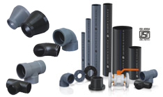
High Density Polyethylene (HDPE) Pipes
Description
High-density polyethylene (HDPE) or polyethylene high-density (PEHD) is a polyethylene thermoplastic made from petroleum. It is sometimes called "alkathene" or "polythene" when used for pipes. HDPE is known for its large strength-to-density ratio. The density of HDPE can range from 0.93 to 0.97 g/cm3 or 970 kg/m3. Although the density of HDPE is only marginally higher than that of low-density polyethylene, HDPE has little branching, giving it stronger intermolecular forces and tensile strength than LDPE.
The difference in strength exceeds the difference in density, giving HDPE a higher specific strength. It is also harder and more opaque and can withstand somewhat higher temperatures (120 °C/ 248 °F for short periods, 110 °C /230 °F continuously). High-density polyethylene, unlike polypropylene, cannot withstand normally required autoclaving conditions.
Pipe
The number one characteristic that sets HDPE apart from other pipe types is that it can be made to be flexible. This quality opens HDPE pipe up to a different world of applications than rigid pipe. Another quality of HDPE is that it can melted and re-solidified a limitless number of times without losing any of its favorable qualities. For this reason, most HDPE pressure pipe is made to be 'butt welded'. This is where the ends of two sections of pipe are melted and then pushed and held together, forming a single pipe.
Fittings
Fittings include Bend (Butt & Socket Weld), Tee (Butt & Socket Weld), Long Neck Pipe End, Short Neck Pipe End, Blind Flange, Reducer and Hose Nipple - Flange End
Marking and uniformity: Pipe and fittings made from ASTRAL ® HP HDPE compounds shall be clearly marked with the manufacturer's name ot trademark, material designation applicable ASTM Standard.
BASIC USE
ASTRAL CORZAN. HP HDPE pipe and fittings are intended for use in both pressure and drain applications in general chemical manufacturing plants, pulp and paper plants, waste water treatment plants, metal treating/electroplating plants, water purification plants, and food processing plants where excellent resistance to corrosion from a wide range of chemicals, acids, and bases at temperatures upto 200 °F is required.
SYSTEM DESIGN
System design shall be in accordance with standard industry practice for thermoplastic industrial piping systems and shall take into consideration such factors as pressure and flow requirements, friction loss, operating temperatures, support spacing, anchoring, bracing and thrust blocking, temperature correction factors, joining methods, chemical environment, collapse and loading, and thermal expansion and contraction.
BENEFITS
- Corrosion resistance. Does not r ust, rotor cor rode.
- Leak tight. Heat-fused joints create a homogenous, monolithic system. The fusion joint is stronger than the pipe.
- Maintains optimum flow rates. Does not tuberculate, has a high resistance to scale or biological build-up.
- Excellent water hammer characteristics. Designed to withstand surge events.
- High strain allowance. Virtually eliminates breakage due to freezing pipes.
- Additional cost savings are achieved by lower instance of repairs.
- With no exfiltration or infiltration, potable water losses and groundwater nuisance treatment costs encountered in traditional piping systems are eliminated.
- Material of choice for trenchless technology. Used in directional boring, plowing, river crossings, pipe bursting and sliplining
- Fewer fittings due to pipe flexibility. Allowable bending radius of 20 to 25 times outside diameter of pipe
- Lighter equipment required for handling and installation than with metallic materials
- Eliminates the need for thr ust blocking. Heat fused joints are fully restrained
- Light weight and longer lengths allow for significant savings in labor and equipment
WALL THICKNESS CHART OF 'AERO' HDPE PIPES IS : 4984 : 1995 WITH LATEST AMENDMENT
Table 2.1: MATERIAL GRADE PE 63
Nominal |
PN2.5 |
PN4 |
PN6 |
PN8 |
PN10 |
|||||||
Dia. |
Min. |
Max. |
Min. |
Max. |
Min. |
Max. |
Min. |
Max. |
Min. |
Max. |
||
| 20 | 2.3 | 2.8 | ||||||||||
25 |
|
|
|
|
|
|
2.3 |
2.8 |
2.8 |
3.3 |
||
32 |
|
|
|
|
2.3 |
2.8 |
3.0 |
3.5 |
3.6 |
4.2 |
||
40 |
|
|
2.0 |
2.4 |
2.8 |
3.3 |
3.7 |
4.3 |
4.5 |
5.2 |
||
50 |
|
|
2.4 |
2.9 |
3.5 |
4.1 |
4.6 |
5.3 |
5.6 |
6.4 |
||
63 |
2.0 |
2.4 |
3.0 |
3.5 |
4.4 |
5.1 |
5.8 |
6.6 |
7.0 |
7.9 |
||
75 |
2.3 |
2.8 |
3.6 |
4.2 |
5.3 |
6.1 |
6.9 |
7.8 |
8.4 |
9.5 |
||
90 |
2.8 |
3.3 |
4.3 |
5.0 |
6.3 |
7.2 |
8.2 |
9.3 |
10.0 |
11.2 |
||
110 |
3.4 |
4.0 |
5.3 |
6.1 |
7.7 |
8.7 |
10.0 |
11.2 |
12.3 |
13.8 |
||
125 |
3.8 |
4.4 |
6.0 |
6.8 |
8.8 |
9.9 |
11.4 |
12.8 |
13.9 |
15.5 |
||
140 |
4.3 |
5.0 |
6.7 |
7.6 |
9.8 |
11.0 |
12.8 |
14.3 |
15.6 |
17.4 |
||
160 |
4.9 |
5.6 |
7.7 |
8.7 |
11.2 |
12.6 |
14.6 |
16.3 |
17.8 |
19.8 |
||
180 |
5.5 |
6.3 |
8.6 |
9.7 |
12-6 |
14.1 |
16.4 |
18.3 |
20.0 |
22.2 |
||
200 |
6.1 |
7.0 |
9.6 |
10.8 |
14.0 |
15.6 |
18.2 |
20.3 |
22.3 |
24.8 |
||
225 |
6.9 |
7.8 |
10.8 |
12.1 |
15.7 |
17.5 |
20.5 |
22.8 |
25.0 |
27.7 |
||
250 |
7.6 |
8.6 |
12.0 |
13.4 |
17.5 |
19.5 |
22.8 |
25.3 |
27.8 |
30.8 |
||
(All dimension in mm.) |
||||||||||||
Table 2.2: MATERIAL GRADE PE 80
| Nominal | PN2.5 | PN4 | PN6 | PN8 | PN10 | |||||||
| Dia. | Min. | Max. | Min. | Max. | Min. | Max. | Min. | Max. | Min. | Max. | ||
| 20 |
|
|||||||||||
25 |
|
|
|
|
|
|
|
|
2.3 |
2.8 |
||
32 |
|
|
|
|
|
|
2.4 |
2.9 |
3.0 |
3.5 |
||
40 |
|
|
|
|
2.3 |
2.8 |
3.0 |
3.5 |
3.7 |
4.3 |
||
50 |
|
|
2.3 |
2.8 |
2.9 |
3.4 |
3.8 |
4.4 |
4.6 |
5.3 |
||
63 |
|
|
2.5 |
3.0 |
3.6 |
4.2 |
4.7 |
5.4 |
5.8 |
6.6 |
||
75 |
|
|
2.9 |
3.4 |
4.3 |
5.0 |
5.6 |
6.4 |
6.9 |
7.8 |
||
90 |
2.3 |
2.8 |
3.5 |
4.1 |
5.1 |
5.9 |
6.7 |
7.6 |
8.2 |
9.3 |
||
110 |
2.7 |
3.2 |
4.3 |
5.0 |
6.3 |
7.2 |
8.2 |
9.3 |
10.0 |
11.2 |
||
125 |
3.1 |
3.7 |
4.9 |
5.6 |
7.1 |
8.1 |
9.3 |
10.5 |
11.4 |
12.8 |
||
140 |
3.5 |
4.1 |
5.4 |
6.2 |
8.0 |
9.0 |
10.4 |
11.7 |
12.8 |
14.3 |
||
160 |
4.0 |
4.6 |
6.2 |
7.1 |
9.1 |
10.3 |
11.9 |
13.3 |
14.6 |
16.3 |
||
180 |
4.4 |
5.1 |
7.0 |
7.9 |
10.2 |
11 .5 |
13.4 |
15.0 |
16.4 |
18.3 |
||
200 |
4.9 |
5.6 |
7.7 |
8.7 |
11.4 |
12.8 |
14.9 |
16.6 |
18.2 |
20.3 |
||
225 |
5.5 |
6.3 |
8.7 |
9.8 |
12.8 |
14.3 |
16.7 |
18.6 |
20.5 |
22.8 |
||
250 |
6.1 |
7.0 |
9.7 |
10.9 |
14.2 |
15.9 |
18.6 |
20.7 |
22.8 |
25.3 |
||
(All dimension in mm.) |
||||||||||||
Table 2.3: MATERIAL GRADE PE 100
| Nominal | PN6 | PN8 | PN10 | |||||
| Dia. | Min. | Max. | Min. | Max. | Min. | Max. | ||
| 20 | ||||||||
25 |
|
|
|
|
|
|
||
32 |
|
|
|
|
2.4 |
2.9 |
||
40 |
|
|
2.4 |
2.9 |
3.0 |
3.5 |
||
50 |
2.3 |
2.8 |
3.0 |
3.5 |
3.7 |
4.3 |
||
63 |
2.9 |
3.4 |
3.8 |
4.4 |
4.7 |
5.4 |
||
75 |
3.5 |
4.1 |
4.5 |
5.2 |
5.6 |
6.4 |
||
90 |
4.1 |
4.8 |
5.4 |
6.2 |
6.7 |
7.6 |
||
110 |
5.0 |
5.7 |
6.6 |
7.5 |
8.1 |
9.2 |
||
125 |
5.7 |
6.5 |
7.5 |
8.5 |
9.2 |
10.4 |
||
140 |
6.4 |
7.3 |
8.4 |
9.5 |
10.3 |
11.6 |
||
160 |
7.3 |
8.3 |
9.6 |
10.8 |
11.8 |
13.2 |
||
180 |
8.2 |
9.3 |
10.8 |
12.1 |
13.3 |
14.9 |
||
200 |
9.1 |
10.3 |
12.0 |
13.4 |
14.8 |
16.5 |
||
225 |
10.0 |
11.6 |
13.5 |
15.1 |
16.6 |
18.5 |
||
250 |
11.0 |
12.8 |
15.0 |
16.7 |
18.4 |
20.5 |
||
|
|
|
|
(All dimension in mm.) |
||||
PP/PPH' AERO' PIPES AS PER DIN: 8077
| Nominal | 2.5KG/CM2 | 4KG/CM2 | 6KG/CM2 | 10KG/CM2 | 10KG/CM2 |
| Dia. | THK | THK | THK | THK | THK |
| 20 | 2.5 | 2.8 | |||
25 |
|
|
2.7 |
3.5 |
|
32 |
|
|
3.0 |
4.5 |
|
40 |
1.8 |
2.3 |
3.7 |
5.8 |
|
50 |
2.0 |
2.9 |
4.6 |
6.9 |
|
63 |
2.5 |
3.6 |
5.8 |
8.7 |
|
75 |
2.9 |
4.3 |
6.9 |
10.4 |
|
90 |
3.5 |
5.1 |
8.2 |
12.5 |
|
110 |
4.3 |
6.3 |
10.0 |
15.2 |
|
125 |
3.1 | 4.9 |
7.1 |
11.4 |
17.3 |
140 |
3.6 | 5.4 |
8.0 |
12.8 |
19.4 |
160 |
3.9 | 6.2 |
9.1 |
14.6 |
22.1 |
180 |
4.4 | 7.0 |
10.2 |
16.4 |
|
200 |
4.9 | 7.7 |
11.4 |
18.2 |
|
225 |
5.5 | 8.7 |
12.8 |
20.5 |
|
250 |
6.1 | 9.7 |
14.2 |
22.8 |
|
|
|
|
(All dimension in mm.) |
||
Bend (Butt & Socket Weld)
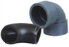
Available M.O.C.
- For Butt Weld- PP, HDPE, PVDF
- For Socket Weld - PP, PVDF
Butt Weld
- Size: 20mm to 200mm
Socket Weld
- Size: 20mm to 160mm
Tee (Butt & Socket Weld)
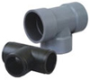
Available M.O.C.
- For Butt Weld- PP, HDPE, PVDF
- For Socket Weld - PP, PVDF
Butt Weld
- Size: 20mm to 200mm
Socket Weld
- Size: 20mm to 160mm
Long Neck Pipe End
Available M.O.C.
- PP, HDPE, PVDF
- Size: 20mm to 630mm
Short Neck Pipe End
Available M.O.C.
- PP, HDPE, PVDF
- Size: 20mm to 200mm
Blind Flange
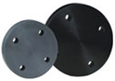
Available M.O.C.
- PP, HDPE, PVDF
- Size: 20mm to 500mm
Reducer
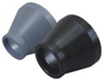
Available M.O.C.
- PP, HDPE, PVDF
- Size: 20mm to 630mm
Hose Nipple - Flange End
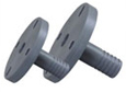
Flage Drilled:
- Universal hole (Capsule hole)
Suitable for all PCD Standards
- Size : 1" to 4"